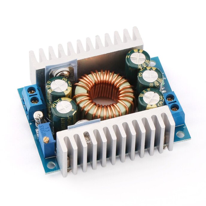
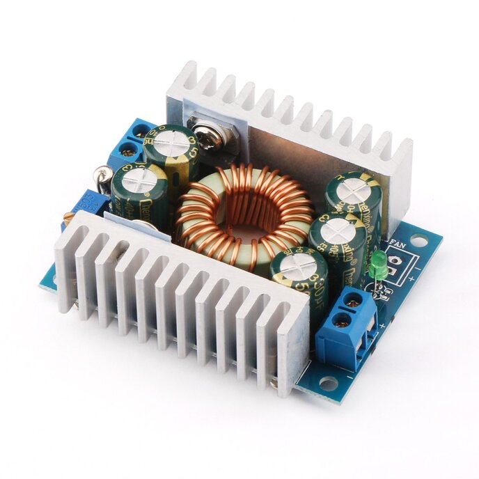
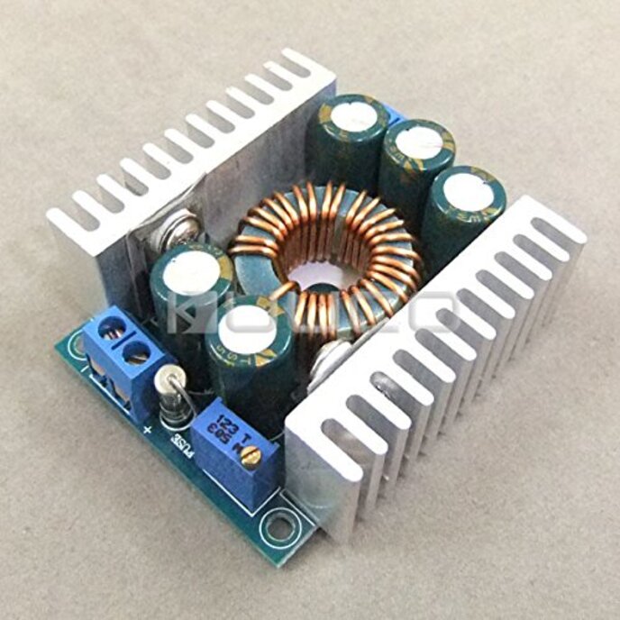
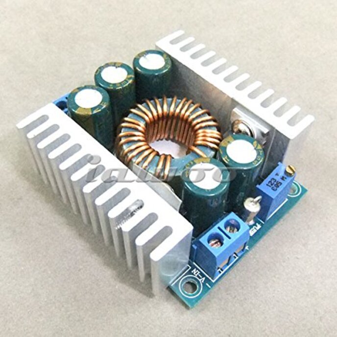
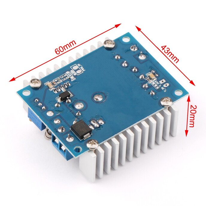
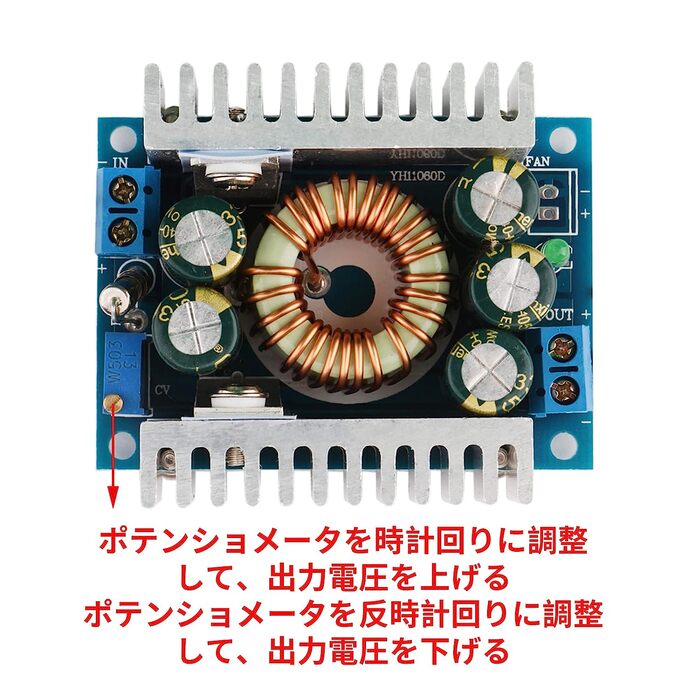
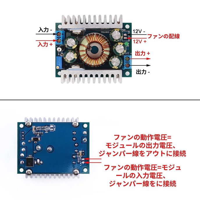
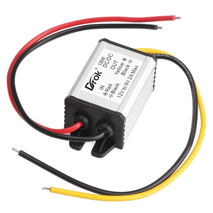
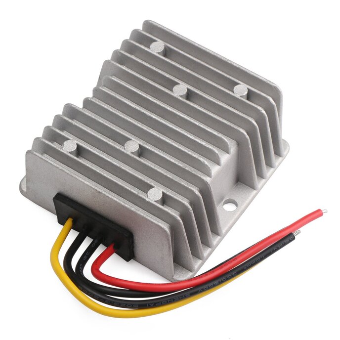
I'll start this review by saying that I like this module. It seems very well constructed, and it is a wonder of Chinese manufacturing that it can be sold for this low price. Try pricing out the cost of the various components and heat sinks, and you'll see what I mean. On the other hand, along with the low price, there will be some infant mortality failures, so you may get the occasional "smoker". I purchased this converter as the front end regulator of a programmable bench power supply that I am building. I only need 3A maximum at 3V - 26V out of it, so I haven't tested it beyond those levels. I can say that the module hardly gets warm under these conditions. Good heat sinking and decent efficiency from the on-board switcher. However, there seems to be some missing information as to the actual specs of the module. One place says 30V maximum input voltage, and in another in the spec says 40V max. So which is it? For the record, I'm going to be powering it from a 24Vac transformer with a full-wave rectified voltage of about 32V, so it makes a difference to me. One reviewer thinks this uses a XL4012 buck converter, while another thinks it's an XL4015. You can't see any labels on the regulator package without desoldering several components, which I didn't want to do. So, to try to answer these questions, I did some testing. First, using a digital oscilloscope, I measured a switching frequency of about 180kHz, with some variation under load. (The peak-to-peak noise voltage under load was about 60mV.) I also measured an on-board reference voltage at the feedback pin of 1.25V. These results rule out the XL4012 which switches at 300kHz with an on-board reference of 0.8V. (As a side note, XLSemi no longer lists the XL4012 as a product - likely it's been obsoleted.) The XL4015 is still a candidate, however. It has the right switching frequency and reference voltage, but it's only rated for 5A continuous. However, on XLSemi's product page (http://www.xlsemi.com/product.html), they list the XL4016 which looks exactly like the spec for this DROK regulator. If you pull up the data sheet for the XL4016 (http://www.xlsemi.com/datasheet/XL4016%20datasheet.pdf), you see: 1) It's rated for 40V input voltage (which makes me happy) 2) it's rated for 8A continuous output (with proper heat sinking) 3) it has a 180kHz switching frequency and 1.25V reference voltage I did some further measurements on the module itself. The spec on the XL4016 says that the minimum input voltage is 8V. However, when I set the output voltage to 3.0V and drove a 2ohm load (1.5 amp output), I was able to run the input voltage down to 4.05V before the regulator started dropping out. So it does work fine at lower voltages than the 8V in the XL4016 spec, but with somewhat increased dropout voltage. Lastly, I looked at the voltage setting resistors. The potentiometer is 50 kohm. The adjustable output voltage is set by the following equation: Vout = 1.25V *( R2/R1 + 1), where R2 is the setting of the pot, and R1 is a fixed 1.5kohm resistor (a small surface mount component located on the bottom of the board right across from the regulator feedback input pin). Of course this equation is true only if the input voltage exceeds Vout by at least the drop out voltage. Someone commented that they want to replace the potentiometer with a digital pot. I also plan to try that. But it's not as simple as just dropping in a digital pot. Almost the full output voltage appears across the pot R2, and very few digital pots will withstand more than 5V. So you will likely blow up the digipot if you drop one in. There are some digipots out there that can withstand higher voltages, but they are surface mount components. And I personally prefer to work with through-hole components, because I don't like having to design a printed circuit board when I'm trying out new circuits for a design. There is a way, however, to use the low voltage digital pots in this kind of application. More on that later, perhaps, if people are interested. Post Note: (3/15/15) I was able to replace the 50k potentiometer with a digital potentiometer (8 bit) and it works beautifully, giving 100mV step resolution in my application. To get around the 5V maximum voltage limitation of the digipot that I used, it required adding a few extra components - basically adding a secondary opamp feedback circuit. Pretty simple, and it is possible to increase the resolution further if needed.